|
|
E-CELL2 User's Manual
|
Chapter 3 E-CELL2 Basic Operation [ Chapter 1 : Chapter 2 : Chapter 4 : Chapter 5 ][ Top ] |
1 Introduction
This chapter explains basic operation of the E-CELL2 System. Please refer to Chapter 2 if needed for Cygwin and E-CELL2, since it is explained on the assumption that its basic operation has been already mastered by the user in " Chapter 2 Tutorial " .
Although there are the GUI mode and the batch mode in E-CELL2, this chapter explains focusing on operation of the GUI mode.
First, " Section 2 Operation Basics " briefly describes the GUI mode first how to start and end the E-CELL2 System. The way of operating the batch mode is explained in " Section 2.9 Batch mode and Logger " .
The Logger is a mechanism, which was first implemented by the E-CELL2 System and saves the result of a simulation on real time. Detailed operation of E-CELL2 is described in the following " Section 3 E-CELL Interface. " The following " Section 4 E-CELL2 script file " explains the script file which raises the operativity of the E-CELL2 system in detail.
In order to perform a simulation, the E-CELL2 System a rule file, or the structured data file.
The details of this rule file are to be explained in Chapter 4. Construction of a new Reactor may be required to perform new modeling. The Chapter 5 explains the Reactor in detail.
If these are all read, you will be able to make the fundamental modeling in the E-CELL2 system.
Note that there are limitations, in which the numerical accuracy is subject to 64 bits in the GUI mode, and 80 bits in the batch mode.
2 Operation Basics
2.1 Starting the E-CELL2 System
To start the E-CELL2 System, startup Cygwin first, then change current directory with the batch file for starting of E-CELL2 System with the command " cd " .
The standard installation place for standard reactor models is " C:\E-CELL2\standard " , and this is expressed as " /cygdrive/c/E-CELL2/standard " on Cygwin. Similarly, in an erythrocyte model, " C:\E-CELL2\erythrocyte " is the standard installation place, and " /cygdrive/c/E-CELL2/erythrocyte " corresponds to this directory on Cygwin. In order to start the GUI mode of E-CELL2, the following batch file should be executed.
% ./ECELL2.BAT
Or click ECELL2.BAT on Explorer of Windows etc. If the software was installed by default, E-CELL2 for standard reactors is started up by clicking the shortcut on the desktop of your PC.
The control panel for the E-CELL2 system appears on your desktop after some warning messages from the software are shown in the command prompt.
If the script file 'default.ecs' is in the current directory when starting E-CELL2, the file will be processed automatically by the software. Note that if there is no 'Load Rule' command in this script file, and it calls Interface or there is a Run command, it is impossible to run the software. The details of the Script File are explained in Section 4 of this chapter.
Launching configurations can be adjusted by specifying the following options at the command line when starting up ECELL2.BAT:
| -a classname | Specifies user default accumulator (See Chapter 4 Section2.3); |
| -c | Loads save time of .cs file. This option applies only when a .cs file has been specified in a Script File using the LoadCellState command (See Section 3.5). If this option is used when the E-CELL2 simulation time is 0, the specified .cs file is loaded and simulation resumes from the recorded save time of that file. Under any other circumstances, simulation time will not change regardless whether a .cs file(See Section 2.7) has been specified or not ; |
| -d | Activates Debug Mode |
| -f filename.ecs | Loads the specified Script File |
| -h | Displays option list. |
| -t directory_name | Specifies the directory of temporary files for virtual memory; |
| -u integer | Defines the frequency of Postern Reactor initialization. (See " Postern Reactors " in Chapter 5); |
2.2 Loading Rule Files
Rule Files (suffix: .eri) are data files which contain information necessary for running simulations (i.e. the cell model), and must be loaded by the E-CELL2 application before a simulation can be started. To load Rule Files, choose " Load Rule " from the File menu in the Control Panel.
Beware not to load rule files twice. E-CELL2 ignores it.
2.3 Loading Script Files
Script Files (suffix: .ecs) can be used to automate the control of simulations and the E-CELL2 Interfaces.
If " default.ecs " , a Script File,
exists in the current directory when
E-CELL2 is executed, that file will automatically
be loaded. Note that loading an erroneous " default.ecs " file will
cause the program to terminate. So if you are using a " default.ecs "
file, make sure that it doesn't contain any bugs!
Script files are for controlling a simulation and each interface. To load Script Files, choose " Load Script " from the File menu in the Control Panel. Select the desired Script File from the File Selection Window. Unlike Rule Files which must be loaded before every simulation, Script Files are purely for the convenience of the user. It is therefore not necessary to create or load Script Files to run an E-CELL2 simulation.
Refer to -f option for launching configurations.
2.4 Running Simulations
To run a simulation, click " Start " on the Control Panel after loading a
Rule File. The simulation will begin, and the elapsed time will be
displayed in the time counter. Click " Stop " to terminate the simulation.
Clicking the " Step " button will run the simulation one time increment,
or 'step', at a time.
Note that numerical accuracy in simulations is limited in 64 bits for the GUI mode and in 80 bits for the batch mode.
2.5 Changing the Step Size
A Step is one unit of simulation time in which the amount of substances is updated to reflect the changes due to reactions which have occurred since the previous Step. The default length of this time interval, or the default Step size, is 1/1000s. Step size can be adjusted by choosing the " Preference Window " from the Windows menu and typing a positive value in the Step Size text box. Adjustments can also be made by specifying step size in Script Files. Although the required compute time for a simulation can be shortened by using a larger Step size, this will also lower the precision of the simulation. Similarly, by using a smaller simulation Step size, higher precision can be obtained at the cost of compute time.
2.6 Simulation Results
The user interface is updated once every 100 calculation cycles. This interval can be adjusted by specifying the desired number of cycles in Script Files or preference window.
2.6.1 Tracers
Tracers display simulation results using a 2-dimensional graph which shows the changes in the number of molecules (or concentration) of Substances, or the activity of Reactors over time. To open a new Tracer, click " Tracer " from the NewInterface menu in the Control Panel. To add a new Substance or Reactor to the Tracer, click " Add " to open the EntrySelector. Select the Substance or Reactor to be displayed in the Tracer.
The definition of a Substance may include molecules, ions, radicals and any other particles. Note that all particles are classified as " molecules " in this manual.
The selected Substances and Reactors are each represented by a color in the " Traces Area " . Results of each trace are displayed in the Graph Area as a line, the color of which matches the color of the box in the Traces Area.
2.6.2 Substance Window
The Substance Window is used to display and/or alter the amount of a selected Substance. To open a Substance Window, select " SubstanceWindow " from the NewInterface menu in the Control Panel. When the EntrySelector appears, choose the desired Substance and click " OK " .
The Substance Window displays the SubstanceID, name, number of molecules and concentration of the selected Substance. When the simulation is temporarily stopped, the number of molecules or concentration can be altered manually by clicking on the current value and entering the desired value. The number of molecules can be also adjusted by clicking on the up and down buttons in the lower part of this window.
2.6.3 Reactor Window
The Reactor Window displays the activity of a selected reactor, as well as its substrates, products and other information. To open a Reactor Window, select " Reactor Window " from the NewInterface menu of the Control Panel and open the EntrySelector. Select the necessary Reactor and click " OK " .
The ReactorWindow displays Reactor class, entry name, and the reaction name. The activity per second is displayed at the bottom.
The Reactor Window will be initially in the Simple Display Mode. To see the details of substrates and products involved in the reaction, click the " Show lists " button, which is located in the upper left. The display area will be extended to show the lists of reaction substrates, products, catalysts and effectors.
2.7 Saving Simulation Results
Graphical data from the simulation can be saved by clicking " Save " in the
Tracer which is located in the down left. A new directory Data/ will be created in the directory
where the E-CELL2 program was executed.
The Data directory will contain subdirectories Substance
and Reactor that follow the System tree
structure. Simulation data of all substances and
reactors will be saved in ecd format in
their respective subdirectories.
In E-CELL2, time, quantity, an average quantity, the maximum quantity, the minimum quantity , the average concentration , the maximum concentration, and the minimum concentration (which are not be out-putted in E-CELL1) are out-putted. Data within ecd files are preceded by the following headers;
| key word | value |
|---|---|
DATA | name of data |
SIZE | number of columns and rows |
LABEL | legend of each column |
NOTE | optional comment |
The end of the header is indicated with a string of more than five
" - " s,
and is followed by the simulation data. The end of the file is
indicated by three forward slashes, " /// " .
Below is an example of an ecd file generated by E-CELL2.
DATA: /CELL/CYTOPLASM:SA:Quantity
SIZE: 4 12
LABEL: time quantity
NOTE:

----------------------
0.10000000000000008     1000000 1000000 10000
0.20000000000000016     1000000 1000000 10000
0.300000000000000192    1000000 1000000 10000
0.40000000000000032     1000000 1000000 10000
0.50000000000000032     1000000 1000000 10000
0.600000000000000384    1000000 1000000 10000
0.700000000000000512    1000000 1000000 10000
0.80000000000000064     1000000 1000000 10000
0.90000000000000064     1000000 1000000 10000
1.00000000000000064     1000000 1000000 10000
1.0999999999999896      1000000 1000000 10000
1.19999999999997856     1000000 1000000 10000
///
When saving whole cell state information of the model at a given time during a simulation, select " SaveCellState " from the File Menu in the Control Panel. Cell state data is saved with the file extension " .cs " . This information can be reloaded to resume the simulation at a later stage by selecting " LoadCellState " from the same menu.
2.8 Shutting Down the E-CELL2 System
Choose " Quit " from the File menu of ControlPanel to shut down the E-CELL2 System. A confirmation dialog window will appear. Click " OK " to confirm that you want to quit, and the program will exit.
2.9 Batch mode and Logger
The batch mode, which can be used on the command line, is offered in E-CELL2 System. Start Cygwin and using " cd " command, change current directory where E-CELL2 is installed. In standard installation, " C:\E-CELL2\standard " is where E-CELL2 for standard reactors exists, and it is regarded as " /cygdrive/c/E-CELL2/standard " on Cygwin. The version, or E-CELL2 for the human erythrocyte model, is in " C:\E-CELL2\erythrocyte " and the directory is regarded as " /cygdrive/c/E-CELL2/erythrocyte " on Cygwin.
Typing " ECELL2BB.BAT -h " will display the list of options. These are the same as those of the GUI mode (see Section 2.1). The batch file of MS-DOS, or E-CELL2B.BAT, describes the PATH to the directory where the Reactor libraries(suffix : .dll) are is stored. They are linked dynamically with the core of E-CELL2. It is necessary to specify the DLL storing folder for the batch modes (e. g. DLLRB) in PATH. In order to perform a simulation with the batch mode, it is necessary using " -f " to read a script file (suffix : ecs). Typing only " ECELL2BB.BAT " will load " default.ecs " . Refer to Section 4 of this chapter about a script file.
% ECELL2BB.BAT -f filename.ecs
The following are the contents of ECELL2BB.BAT.
SET PATHSAV=%PATH% PATH=WIN-BCC;DLLRB;%PATH% ecell2b.exe %1 %2 %3 %4 %5 PATH=%PATHSAV% |
If the mechanism " Logger " , which was first implemented in E-CELL2, is used, it will become possible to record the state of a cell at any time during a simulation. This function was mainly mounted for the purpose of use with the batch mode. Refer to " Section 4.5 List of Script File Commands " for how it is used.
3 E-CELL Interfaces
3.1 Control Panel
The Control Panel is an interface for controlling the main functions of the E-CELL2 system, such as loading files, invoking other interfaces, running simulations, and shutting down the program.
Figure.1 Control Panel
- Control Panel Menu List
-
File Load Rule Loads Rule File Load Script Loads Script File Load Cell State Loads Cell State Save Cell State Saves Cell State Quit Shuts down E-CELL2 System NewInterface Tracer Displays Tracer Substance Window Displays SubstanceWindow Reactor Window Displays ReactorWindow Windows Message Window Displays MessageWindow Preference Window Displays Preference Window - Start Button
-
Starts simulation.
- Stop Button
- Stops simulation.
- Step Button
-
Runs one simulation Step.
- Time Counter
- Displays elapsed simulation time (in seconds) in the E-CELL2 system.
3.2 File Selection Window
The File Selector Window appears when a file must be specified to read or write. A destination file is selected and loaded by clicking the " OK " button. To generate a new file, enter a new file name in the text box, and click the " OK " button.
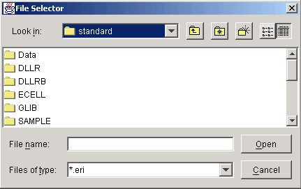
Figure.2 FileSelector
- Folder or File Selection Area
-
All of selectable files or folders are iconified here.
The text box below is filled with a file name by clicking it.
Alternatively, a file can be selected when the file name is double-clicked.
If a folder is clicked, the reference folder is changed to the selected one.
- File Selection
-
The file name, selected in the window above, is shown here.
It can be directly inputted by the user. The input is completed by hitting
the return key, or clicking the " OK " button.
- File Type
-
A regular expression described here filters the items in the area above.
By default, the system expects the files with the standard suffix(e.g.,
*.ecs), according to the situation. In order to change a filter, click File Type and chose another file type.
- OK Button
-
Loads the file currently displayed in the Selection Area.
- Cancel Button
-
Cancels file selection and closes the File Selector.
3.3 Tracer
The Tracer displays changes in the amount of Substances and Reactors' activity over time, using a 2-dimensional graph. The Tracer can display a maximum of 8 Traces at any one time.
Figure.3 Tracer
- Traces Area
-
Lists Substance and
Reactor names displayed in this Tracer.
The color of the name of a Substance or Reactor corresponds to
the color of its line in the Graph Area.
Clicking the left mouse button on the Toggle
button hides its line in the Graph Area.
Clicking the right mouse button on the Toggle button opens a
Substance or Reactor Window, depending on the selected button.
Note that the Tracer can display a maximum of 8 Traces at any
one time.
- Graph Area
-
Simulation results are displayed as line graphs. The vertical axis
represents the number of molecules (or concentration), and the
horizontal axis represents time.
- When multiple Tracers are in use, you can " mark " a common
co-ordinate for all Tracers by clicking the left mouse button at any
position within the Graph Area. A marker as a gray cross will appear in each
Tracer at the same co-ordinate as in the Tracer in which the
co-ordinate was selected. Click anywhere outside the Graph Area
(but still within the Tracer) to get rid of the marker.
- Any region within the Graph Area can be magnified by dragging the
black rectangle with the right mouse button. Double click on the right mouse
button to return to the default view.
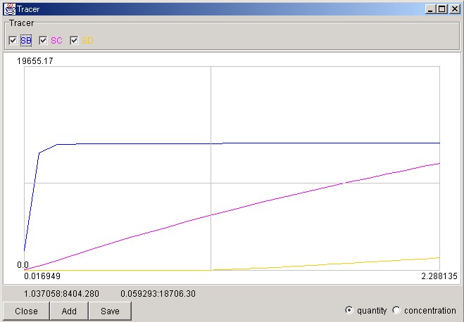
Figure.4 Tracer (Enlarged Display)
- When multiple Tracers are in use, you can " mark " a common
co-ordinate for all Tracers by clicking the left mouse button at any
position within the Graph Area. A marker as a gray cross will appear in each
Tracer at the same co-ordinate as in the Tracer in which the
co-ordinate was selected. Click anywhere outside the Graph Area
(but still within the Tracer) to get rid of the marker.
- Co-ordinates Area
-
Co-ordinates on the left correspond to the position of a
marker, while co-ordinates on the right correspond to the position
of the cursor.
- Close Button
-
Closes Tracer.
- Add Button
-
Opens EntrySelector to display the lists of available
Substances and Reactors which
can be loaded into the Tracer.
- Save Button
- Saves the current results within this Tracer as time series data. " Time " , " value at the moment -- " , " average value " , " maximum value " , and " minimum value " are saved as 5 sequence form for the data.
3.4 EntrySelector
The EntrySelector is used to select Substances and Reactors to be loaded into Interfaces. Click the folder icon in the System Selection Dialog to display the contents of the system. Select a Substance or Reactor from Substance Reactor Selection Dialog and click " OK " . If the EntrySelector was opened from a Tracer, you can switch between the lists of Substances or Reactors using the Primitive Selector Button.
Figure.5 EntrySelector
- Primitive Selector Button
-
Switches the display between the lists of
Substances and Reactors when opened from a Tracer.
- SystemSelection Dialog
-
The Systems which are present in the current model
are displayed in a hierarchical fashion. Click on the folder icon
to display subclasses.
- Substance, ReactorSelection Dialog
-
Either Substances or Reactors are
displayed. Multiple files can be selected by dragging the
cursor down the list, or by selecting file names while pressing
the Ctrl key.
- OK Button
-
Loads the Substance or Reactor chosen in the Substance, ReactorSelection Dialog.
- Cancel Button
-
Cancels file selection and closes the Entry Selector
3.5 Substance Window
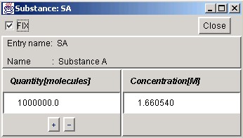
Figure.6 Substance Window
- FIX Button
-
Fixes the number of molecules, keeping it constant throughout the
simulation, if the " FIX " button checked.
- Quantity Area
-
Displays the number of molecules (quantity) of the
Substance. The quantity can be specified by
entering a value when the simulation is not running.
- Concentration Area
- Displays the concentration of the Substance. The concentration can be specified by entering a value when the simulation is not running.
3.6 ReactorWindow
Normal Display Mode
Figure.7 Reactor Window (Normal Display Mode)
- Hide/Show Button
- Switches to Detailed Display Mode.
Detailed Display Mode
Figure.8 Reactor Window (Detailed Display Mode)
- Hide/Show Button
-
Switches to Normal Display Mode.
- Reaction Substance Display Area
- Displays list of parameters, substrates, products, catalysts, and effectors for this reaction.
3.7 Preference Window
Figure.9 Preference Window
- Step interval
-
Changes the interval of a Step of calculation.
- Update interval
-
Changes the interval by which drawing of Tracer is updated.
4 E-CELL2Script File
4.1 Script Files
Script Files (suffix: .ecs) can be used to automate the control of simulations and the E-CELL2 Interfaces. Since the format of Script Files is plain text, they can be created with any text editor.
4.2 Script File Syntax
Script Files are loaded and parsed line by line. Each command in Script Files must be written within one line, except for the " New Interface " command. Subcommands are written after the command to which they belong (e.g. AddTrace is written after New Interface), and must be preceded by a space or tab character.
Comments begin with the '#' character, which is valid for that line only.
4.3 A Sample Script File
Below is an example of a Script File.
TmpDir /Temp LoadRule sample.eri NewInterface Tracer trace1 AddTrace Substance:/CELL/CYTOPLASM:A AddTrace Reactor:/CELL/CYTOPLASM:R1 SaveAt 45 NewInterface SubstanceWindow test-sw Substance /CELL/CYTOPLASM:A Run 500 Stop |
There are some changes from the E-CELL1 System. The path in which a Reactor exists is described in the startup batch file ECELL2.BAT or ECELL2BB.BAT. Therefore, " ReactorPath " command cannot be used in the script file.
Although TmpDir is the directory where a file is saved temporarily, specifying " /Temp " would make it possible to specify " C:\Temp " , which was created when E-CELL2 System was installed. If it was installed in another drive other than " C : " , " /Temp " must exist directory under this drive. If this temporary directory does not exist, the program abnormally terminates immediately after the simulation is started.
4.4 Commentary on the sample Script File
The above Script File begins with the destination of temporary files in the first line, followed by the specification of the Rule File to be loaded, in the second line.
Commands in lines 4-7 instruct E-CELL2 to open a TracerWindow named Tracer1, designating Substance A, in the line 5 and Reactor B, in the line 6, to be displayed in the Tracer. The subcommand " SaveAt " in the line 7 instructs E-CELL2 to save results of the Tracer1 in 45 seconds after this simulation is started.
Commands in the lines 9 and 10 instruct E-CELL2 to open a Substance Window.
The line 12 sets the running time to 500 seconds in total, and the line 13 declares the termination this simulation.
4.5 List of Script File Commands
| Command | Content |
| Accumulator classname | Specifies Accumulator class to be used instead of System Default. |
| TmpDir directory | Designates file path for saving temporary files generated by the simulation. By default, /Temp( " C:\Temp " )is specified. |
| LoadRule filename | Loads specified Rule File. |
| StepInterval second | Specifies time interval for one step in seconds. The default time interval is set at 0.001 seconds. |
| UpdateInterval count | Specifies the number of calculation cycles to be run before the user interface is updated. By default, the user interface will be updated after 100 calculation cycles. |
| SaveCellStatefilename | Saves simulation state to assigned filename. |
| Loads specified simulation state (.cs file). | |
| Run seconds | Executes simulation for the assigned time interval.(in simulation system) |
| Stop | Stops simulation.No argument. |
| Exit | Quits E-CELL2.No argument. |
| NewInterface interface, name | Creates a new interface. Enter the type of interface to be loaded, followed by its name. |
- Commands for every Interface declared within Command NewInterface
Command Content Geometry(X1)x(Y1)+/-(X2)+/-(Y2)Designates size and co-ordinates of the interface to be displayed. Only one string is accepted in this subcommand. (X1)x(Y1)+/-(X2)+/-(Y2)
(X1) and (Y1) specify the width and height of the window. (X2) and (Y2) specify the x co-ordinates and y co-ordinates in relation to the top left vertex of the window. When the co-ordinate values are positive, the top left-hand corner of the window becomes the base. Negative values set the bottom left-hand vertex of the screen as the base. This function may not be available to some window managers.
As compared to E-CELL1, there is a major difference, in which the location of a generated window, defined by the rule above, is automatically adjusted if it appears partially or totally outside the desktop of your PC.
- Interface Commands
-
- Tracer
Command Content AddTrace [FQPN] Designates the Substance or the Reactor FQPNto be displayed in the Tracer.Not only ID, but also the system and Type which they exist must be specified. SaveAt [seconds] Saves results in Tracer at a specific time. This can also be done by clicking the Save button in Tracer. Enter the time to be recorded in seconds. Note that a new directory "Data/" will be created to store results.
- SubstanceWindow
Command Content Substance [FQEN] Declared only in SubstanceWindow. Opens the Substance Window for the Substance specified in FQEN. Not only SubstanceID, but also the system which it exists must be specified.
- ReactorWindow
Command Content Reactor [FQEN] Declared only in ReactorWindow. Opens the Reactor Window for the Reactor specified in FQEN. Like Substance command, not only ReactorID, but also the system which it exists must be specified.
- Logger
Command Content AddTrace [FQPN] The log of the behave of Substances or Reactors specified in FQEN is recorded. Not only ID, but also the system in which it exists must be specified. A directory "Logger" is made in the current directory, and the files for every Substance or Reactor are recorded in the Logger in the format, same with being made from the SaveAt function of the Tracer. Since it records on a file at any time during execution of the program, the record remains even if E-CELL2 crashes.
- Tracer