|
|
E-CELL2 User's Manual
|
Chapter 2 Tutorial [ Chapter 1 : Chapter 3 : Chapter 4 : Chapter 5 ][ Top ] |
This chapter explains an outline about the feature and the operation of E-CELL2.20. Refer to the details about the theoretical background of E-CELL and the tutorial offered by the E-CELL.Org(http://www.e-cell.org), distributed in the future.
In order to model a cell, which is highly complicated in the real world, abstraction of composition elements is needed. In E-CELL, in order to express the structure of a cell and the chemical reaction in a cell, the "Substance-Reactor Model" is employed. There are the following features in this model.
Note that the concept of a substance (Substance) includes not only chemical molecules, ions or radicals as usual, but also even physical elements like osmotic pressure and volume of a cell.
In E-CELL , it is assumed that concentration of Substance is uniform everywhere inside a cell, by ordinary. Therefore, in order to treat diffusion in E-CELL2, it is expressed as a step function of concentration of a Substance, resulted from two or more systems where the Substance exists in every system uniformly, but its quantity differs among them.
In E-CELL, to carry out the simulation of various phenomena in a cell, both of flux-based reaction and equilibrium-based reaction are implemented.
First, a flux-based (i. e., can be solved as differential equation) chemical reaction is treated as follows inside E-CELL.
An equibrium-based (i. e., can be solved as algebraic equation) chemical reaction is treated as follows.
In terms of the software engineering, E-CELL2 has the following features. First, the part, written in C++, is described for explanation. It is nearly identical to the view of the world, or what is called " ontology ", and it is the framework for modeling a cell and the core of E-CELL2. Such components of software are called " classes " from the viewpoint of object-oriented modeling, and the mechanism for simulation is implemented in interactions among the classes of E-CELL2.

Meanwhile, the different features of E-CELL2 are stated now as compared to E-CELL1.
These were performed to make E-CELL1, working only on the Linux system, more portable to the Windows system. On the other hand, GUI (Graphic User Interface) and the module to interpret an automating script for E-CELL2 are written in Java.
The software, or E-CELL2, can be manipulated through two interfaces. One equips GUI, in which the user can simulate interactive, and the other is for command-line use. Some instructions are given in Chapter 2 only for the GUI type. Please refer to Chapter 3, Section 2.9 "Batch mode and Logger" for explanation of the batch type. Note that precision of the GUI and the batch E-CELL2 is 64 bits and 80 bits, respectively. The less accuracy of the GUI type comes from limitation in numerical calculation in the Java Native Interface (JNI).
Then, let's operate E-CELL2 using a model example. In this section, a metabolic model of human erythrocyte is tried to be run on E-CELL2. Why is an erythrocyte cell suitable as an object of such a simulation? The reasons are as follow.
The main metabolic pathways of the erythrocyte consist of glycolysis, pentose phosphate cycle, and nucleotide synthesis. In addition, there are large amounts of hemoglobin, carrying oxygen. An erythrocyte cell can be considered as a bag full of hemoglobin and has self-regulating components for these metabolic pathways. Although this model aims at reconstruction of realistic metabolic pathways in a human erythrocyte cell, it is expected that conveyance of hemoglobin can be traced by another model in the future.

Assistant Professor Nakayama, Professor Tomita, and their colleagues at Keio University have conducted a research project to reconstruct metabolic pathways of a human erythrocyte cell on the E-CELL system. Please visit the site for introduction of this research (http://www.e-cell.org/poster/ynakayam/ISMB99/ppframe.htm) hosted by the E-CELL.Org for further reading. Only a metabolic model of a normal human erythrocyte is demonstrated this time, but there are some models, being rigorously studied with E-CELL, for anemia caused by genetic abnormalities. Please have a contact with Assistant Professor Nakayama (ynakayam@sfc.keio.ac.jp) if you are interested in these studies.
First, please start Cygwin to simulate the erythrocyte model, and choose Cygwin from [Start] or click the icon on your desktop.

Please use the command "cd" on Cygwin to change the current directory containing E-CELL2.20 for the erythrocyte model. For the details of this command, read the command reference of UNIX or input "man cd", and refer to the displayed manual. In standard installation, the directory, or "C:\E-CELL2\erythrocyte", is the place for this model. Note that a directory path must be described according to the notation in UNIX. Type "./ECELL2.BAT" and hit "Enter" key.

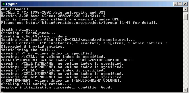
The E-CELL2 for a erythrocyte model starts. If E-CELL2 finds the file "default.ecs" in the same directory as ECELL2.BAT, it reads this file and tries to start a simulation. Since a default.ecs file is prepared for the erythrocyte model of Fig. 4 this time, a demonstration is started automatically. The file "Erythrocyte236.eri" describes parameters and initial values for this simulation.
Generally a file with the extension "ecs" is a script for automating E-CELL2, and for operating E-CELL2 step by step. For details, please refer to Section 2.3 and Section 3.4. The simulation of an erythrocyte model shown in Fig. 4 is controlled by execution of this script. Although calculation with this script stops in 11 seconds, the whole system requires about 10,000 seconds to reach a steady state, generally.

In order to terminate E-CELL2 before the stop command in a script, click "Stop" button of the Control Panel to suspend the simulation, and click [Quit] from the [File] menu.
The operation instructions of E-CELL2 are briefly explained in the following paragraph. If you understand them, let's try many things using E-CELL2.
Before starting practical explanation, a simple model for simulations is introduced. A figure below shows the simplest feedback system called "Toy " by E-CELL modelists.

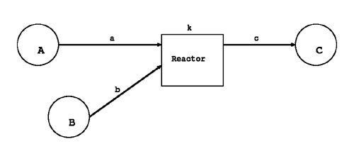
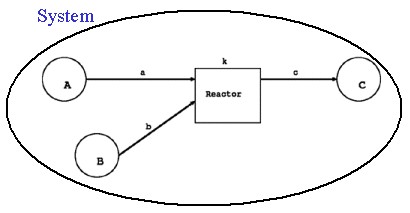
Five Substrate and four Enzyme, oneComplex appear in this model. A Substrate is connected with another via a Reactor (chemical reaction formula), and there are four Reactors. A Reactor indicates a chemical reaction formula like the Michaelis-Menten scheme, for example. In case of a cultured cell, these reactions exist in a Cell, surrounded by culture media as Environment. A Membrane compartmentalizes the external world and the inside of a cell, which is filled with Cytoplasm.
Now, the network of chemical reactions has been depicted as static graph.
However, it is not adequate to begin an actual simulation on E-CELL2. Parameters, such as initial values of Substances and velocities of Reactors must be given in addition to the static network of chemical reactions.
In the E-CELL system, the rule of a simulation, called Rule File, is discriminated by the extension of ".er". Only the file, called Rule Intermediate File, can be directly read by E-CELL, and it is converted from a Rule File using a tool, attached to the E-CELL system. A Rule File is usually discriminated by the extension of ".eri".
Since it is difficult for beginners of E-CELL simulations to describe Rule File from scratch, the tool which creates a Rule File from the spread sheet is also offered as part of the E-CELL system, to support writing a Rule File.
Here, an outline is introduced to make a spread sheet for simulations and convert it into the format of the Rule Intermediate File for 2.
Although there are various kinds of spreadsheet software, a typical one on Windows, or Excel of the Office XP Standard English edition is taken for an example, and bare essentials are described to create a Rule File..

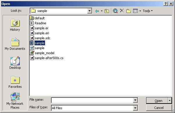
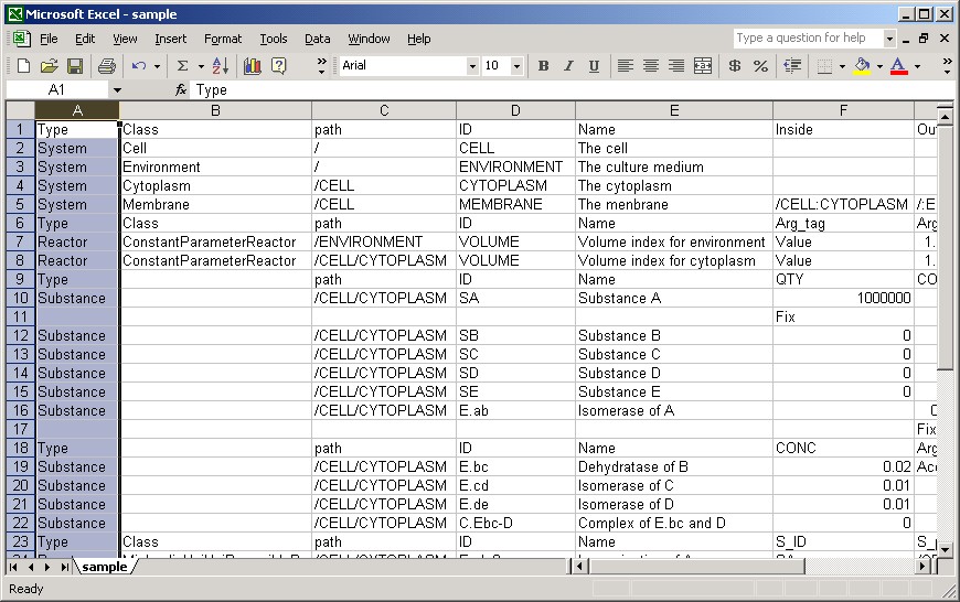
Let's load a sample Rule File of 2 to Excel. Choose [Open] from the [File] menu to open the file selection window. Clicking the icon of a folder, please look for the file "C:\E-CELL2\standard\SAMPLE \sample\sample.txt" and read it into Excel.
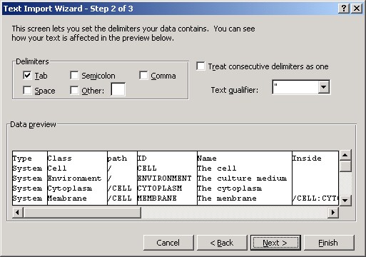
Since the spread sheet for 2 must be tab-delimited, "sample.txt" is also described in this style. Choose the upper radio button and move on to the next.

Please select the "tab" as delimiting character of a field, and move on to the next. If the user's tab-delimited file is hitherto written with other editor programs, the double quotation " must be chosen as text qualifier. Choose "{none}", if nothing is used for quotation marks.
This window is for setting parameters to read each column, but nothing special is needed here. Therefore, click "Finish" to start reading the file.

The network structure of the Toy model in Fig. 8, and description of initial values for reactions and substance qualities were displayed on a spread sheet of Excel. Here, since it aims at explanation of the usage of Excel, explanation of a rule is mentioned later.
In fact, according to the description way of a rule for the simulation, a spread sheet will be created newly or edited descriptions in each cell of the spread sheet will be saved.
The way to save an edited file is explained here. From the [File] menu and choose [Save As] to save it as text in the tab-delimited format -- "Text (Tab delimited)". Note that if you it in the Excel format (with the extension ".xls"), you can not convert the file.
In default installation, the tool to support making a rule file is put on "C:\E-CELL2\tools\rule." If a file, edited for the rule file, is stored at this directory, it will become easy to do the following operations.
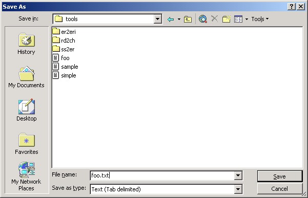
Although a warning message, to tell that the file format is not compatible with "Text (Tab delimited)", is shown on a dialog box, please push the "Yes" button to save the file.

Here is the end of how to use EXCEL for 2.
The following instruction is given for the procedure to convert a spread sheet into a Rule File, and that Rule File into a Rule Intermediate File. Refer to Chapter 4 for the details about Rule File.
Start Excel (or other spreadsheet software, such as Star Suite) and read "sample.txt " and "toy.txt ". The file "toy.txt " is an incomplete file of the Toy model. These files are put in the "tools\rule " directory for tutorials. They are in the directory "C:\E-CELL2\tools\rule ( "/cygdrive/c/E-CELL2/rule " for Cygwin) " in case of standard installation.
It was already explained that there are "System ", "Substance ", and "Reactor " in the Substance-Reactor model of E-CELL. The leftmost column of a spread sheet is called Type, each field is filled with one of them. A System is used in order to show indicate the structure of a cell, or the localization of a substance, and it includes "Environment ", "Cell ", "Membrane ", and "Cytoplasm " typically. Refer to Section 4.2.2 for the detailed explanation about System. Here, keep in mind that embedded structures, such as a cell, can be expressed by distinguishing "Inside " and "Outside ".
The concept of Substance includes many kinds of physical or chemical entities in a broad sense. In the spread sheet read by EXCEL, there is the table below. In the "Toy " model, Substance are materials chemical reactions and enzymes for their reaction catalysis. Substance becomes the enzyme which plays a role for the catalyst of the reaction to the material for a chemical reaction.
Table 2.1 Example descriptions of Substances used as materials for chemical reactions
| Type | path | ID | Name | QTY |
|---|---|---|---|---|
| Substance | /CELL/CYTOPLASM | SA | Substance A | 1000 |
| Fix | ||||
| Substance | /CELL/CYTOPLASM | SB | Substance B | 0 |
| Substance | /CELL/CYTOPLASM | SC | Substance C | 0 |
A Path is the place where Substance exist, and it is described like a directory path of UNIX. The symbol, or ID means the ID of a specified Substance and is an indispensable item. The symbol, or Name is the name of a specified Substance. Either Qty or Conc is mandatory for the Substance, and Qty is the initial value of "Quantity " and Conc is the initial value of "Concentration ". The unit of Conc is mol/l. If Quantity and Conc are assumed to be fixed, the "Fix " tag makes Quantity or Conc fix through a simulation. Refer to Section 4.2.3 about the details of Substance.
The following is description about enzyme.
Table 2.2 Example descriptions of Substances, which catalyze reactions as enzyme
| Type | path | ID | Name | CONC |
|---|---|---|---|---|
| Substance | /CELL/CYTOPLASM | E.bc | Enzyme B | 0.02 |
| Substance | /CELL/CYTOPLASM | E.cd | Enzyme C | 0.01 |
| Substance | /CELL/CYTOPLASM | C.E.bc-SD | Complex of E.bc and SD | 0 |
<Problem>
1.	In  "toy.txt ", a few descriptions of Substance D and Substance E are missing.  Let's fill it up by using  "sample.txt " as reference.
2.	Similarly make up for lacks in descriptions for Isomerase A and Isomerase of D.
On the other hand, Reactors are substantialized chemical reactions. For example, they are defined as follows.
Table 2.3 Example descriptions of Reactor
| Type | Class | path | ID | Name | S_ID | S_path | S_coeff | P_ID | P_path | P_coeff | C_ID | C_path | Arg_tag | Arg_coeff |
|---|---|---|---|---|---|---|---|---|---|---|---|---|---|---|
| Reactor | MichaelisUniUniReactor | /CELL/CYTOPLASM | E.ab-0 | A->B | SA | /CELL/CYTOPLASM | 1 | SB | /CELL/CYTOPLASM | 1 | E.ab | /CELL/CYTOPLASM | KmS | 10 |
| KcF | 5 | |||||||||||||
| Reactor | MichaelisUniUniReactor | /CELL/CYTOPLASM | E.bc-0 | B->C | SB | /CELL/CYTOPLASM | 1 | SC | /CELL/CYTOPLASM | 1 | E.bc | /CELL/CYTOPLASM | KmS | 0.1 |
| KcF | 3 | |||||||||||||
| Reactor | MichaelisUniUniReactor | /CELL/CYTOPLASM | E.cd-0 | C->D | SC | /CELL/CYTOPLASM | 1 | SD | /CELL/CYTOPLASM | 1 | E.cd | /CELL/CYTOPLASM | KmS | 0.1 |
| KcF | 2 |
A Path indicates here the place where a Reactor exists, and it is described like a directory path of UNIX. The symbol, or S_ID, is the sign of a "Substrate ", which means one of starting materials for a chemical reaction and S_Path indicates its location. The symbol, or P_ID, is the sign of "Product ", resulted from the chemical reaction, and P_Path indicates its location. The symbol, or C_ID is the sign of "Catalyst ", which is a chemical substance, promoting or repressing a reaction, and C_Path indicates its location. The constant name, defined by the kind of Reactor, is inputted into an Arg_tag column. The constant value corresponding to Arg_tag is inputted into Arg_coeff.
A Reactor from which its ID begins in "! " is the reactor to handle an algebraic reaction, and is used for describing the reaction which cannot be described by any differential equations. In the "Toy " model, "! EQ-Ebc-D " is the algebraic reactor. A reaction Ebc+SD < - > C.Ebc-D is the reversible in comparison of one in which Ebc and SD produces C.Ebc-D and the other in which C.Ebc-D is decomposed. Its behavior cannot be expressed in a differential equation. Therefore, the "RapidEquibriumPReactor " for rapid equilibrium is used here.
<Problem>
1. Completely describe the reaction of the Reactor D-> E.
Refer to Section 4.2.4 for the details of Reactor. After the work above is finished, save "toy.txt " and start the work to create a Rule File from here onwards.
In order to create a Rule File from a spread sheet, it is necessary to do the following thing.
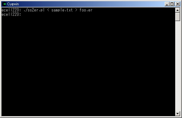
% ./ss2er.pl < input_filename.txt > output_filename.er
Put the name of the file which you actually created into "filename ". To convert a spread sheet into the corresponding Rule File, the Perl script "ss2er.pl ", in the directory "tools\rule ", is used. The output result of this script must be written out to the file with the extension ".er " which usually expresses Rule File.
Now, practical steps are shown below to perform the operation above, by using Cygwin.
First, start Cygwin. Please click the icon of a desktop or choose Cygwin from [Start].
By using the "cd " command, the user can move to the "tools\rule " directory. In standard installation, the tools for rule creation are put on "C:\E-CELL2\tools\rule ". On Cygwin, this directory is recognized, as shown in the following figure.

A Rule File is created from a spread sheet using ss2er.pl. If "toy.txt ", which was completed previously, is used for this purpose, this will be pretty understandable. The Perl language needs to be installed in "/usr/bin/perl " on Cygwin to use this script. When Cygwin is installed from CD-ROM, Perl is also installed.
In this example, "foo.er " is generated from "sample.txt ". "sample.txt " is the spreadsheet of a Toy model.
Read the generated Rule File using the command "less ".

If this command is used, you can view the file per page. Touch "F " key to go forward, "B " key to go backward. Hit "Q " key to quit.
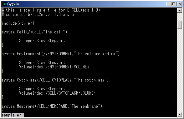
Hit "F " key.
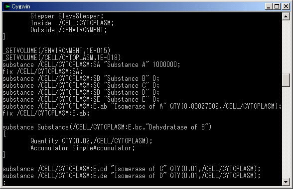
Now the spread sheet was converted to the corresponding Rule File.
In order to perform a simulation by E-CELL2, it is necessary to change a Rule File into the correctly processed Rule Intermediate File.
In order to create a Rule Intermediate File from a Rule File, it is necessary to perform the following operation.
./er2eri.sh base_filename
Input the name of your Rule File without extension " .er. " for "base_filename", since it is automatically attached. Input "foo " if it is "foo.er ". In order to change a Rule File into the Rule Intermediate File, the bash script "er2eri.sh" in the "tools\rule " directory is used. If this bash script is performed, it will be written out to the file with the extension ".eri ", indicating Rule Intermediate File.
Then, practical steps are shown below to perform the operation above, by using Cygwin.
The script file, or "er2eri. sh " is in the same directory as "ss2er.pl " which was used for creating a Rule File. Execute "er2eri.sh ".
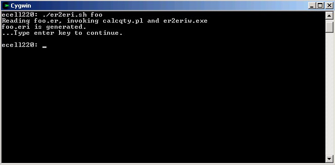
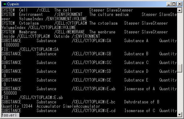
In this example, "foo.eri" is generated from "foo.er". Use the command "less " to see the Rule Intermediate File.
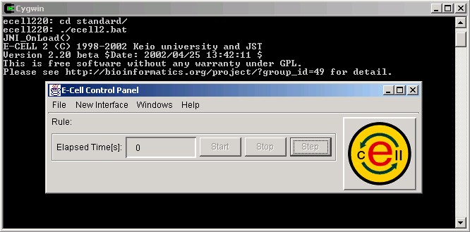
Let's load "foo.eri " into E-CELL2. For simplification, "foo.eri " is copied to the directory for for the standard-reactor model of E-CELL2 ( "standard "). The "cp " command is used for making a copy of the file. In standard installation, "C:\E-CELL2\standard " becomes the directory on which the model for standard reactors is put.

Move to the directory for the standard-reactor model using the "cd " command. Start up E-CELL2 by executing the batch file for E-CELL2.

Until here, all operations are supposed to be performed on the premise that the user is in the directory, which contains tools to make Rule Files and Rule Intermediate Files. In fact, however, it is more convenient if these tools can be used anywhere on Cygwin. To realize this, the environmental variable PATH must include their directory, which is "C:\E-CELL2\tools\rule " by default, and is expressed as "/cygdrive/c/E-CELL2/tools/rule " in the Cygwin manner. Please refer to Chapter 1, Section 3.1 to set the environmental variable PATH. New settings above make you free from "./ ", which means "in the current directory ".
The line feed code is "CR+LF " in Windows, but "LF " in UNIX. Therefore, Rule Files made on Windows cannot be loaded into E-CELL1 on Linux. A tool to remove "CR " is offered as part of E-CELL2, and use it if need be. In the directory as the same as tools for Rule Files, type the following command below. The first argument is the name of an input file and the second is the name of the output one.
./rmcr.exe input-filename output-filename
If C-shell compatible environment is available on Linux, it is also possible to remove "CR " in a file, by using the script "rmcr.csh ". Transfer files made on Windows with this script, then run this script to process a text file, generated on Windows, as the first argument.
This is the end of explanation concerning making Rule Files and Rule Intermediate Files. In the next section, basic operations on E-CELL2 are instructed.
Let's learn fundamental operations of E-CELL2 using a Rule Intermediate File. Control panel will appear first after E-CELL2 is started.
First, a few pull-down menus on the control panel are explained briefly.
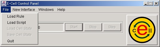
In the [File] menu, there are [Load Rule], [Load Script], [Load Cell State], [Save Cell State] and [Quit] items.
The item [Load Rule] is chosen to read a Rule Intermediate File.
The item [Load Script] is chosen to read a sequentially regulating script for E-CELL2.
The item [Load Cell State] is chosen to resume a simulation by reading a file which recorded the state of E-CELL2.
The item [Save Cell State] is used to save the file, which records the progress of a simulation, for the function above.
Selection of the item [Quit] terminates E-CELL2.
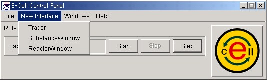
In the [New Interface] menu, there are [Tracer], [SubstanceWindow] and [ReactorWindow] items.
The item [Tracer] is selected to create a [Tracer] window, on which quantity of focused Substance, or activity of focused Reactors.
The item [SubstanceWindow] is chosen to open a window for manipulating a Substance.
The item [ReactorWindow] is chosen to open a window for manipulating a Reactor.
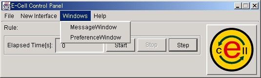
In the [Windows] menu, there are [MessageWindow] and [PreferenceWindow] items .
The item [MessageWindow] is used for displaying the messages from E-CELL2.
The item [PreferenceWindow] is chosen to change the timing of refreshing user interface windows and/or the step-width of simulational calculations of E-CELL2.
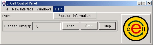
In the [Help] menu, there is the sole item [Version Information], but only the version information is shown even if it is selected.
The above is explanation about the menus on the control panel.
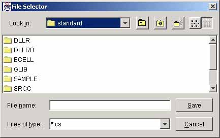
Choose [Load Rule] in the [File] menu in order to read Rule Intermediate File. Since the file selector is displayed, let's click the icon of a file with the extension " .eri " , indicating the Rule Intermediate File, and push the button " Open " .

If the specified file is read normally, it will be displayed as " Condition Good. " on the screen of Cygwin.
Next, open a [Tracer] window to prepare for displaying the quantity of Substance as graph. The Tracer window appears by selection of [New Interface] - [Tracer].
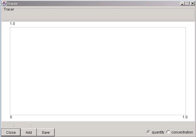
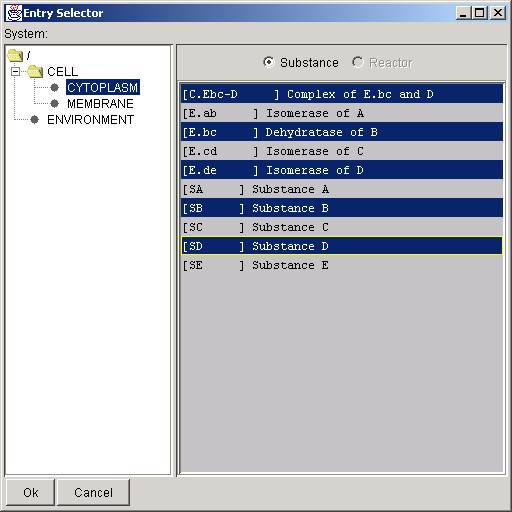
Click the " Add " button in the lower left of Tracer to display an [Entry Selector] window. Click the left panel and choose a Substance, which is located in Cytoplasm.
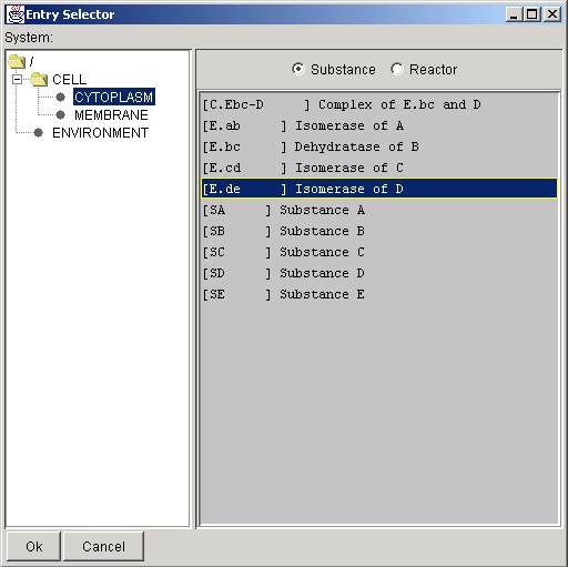
Click the radio button of Substance to display Substance on the right panel. It is also possible to display Reactor by clicking the other.

How to choose two or more Substances or Reactors is explained. In order to choose several ones collectively, click the left button of the mouse, pushing the " Shift " key. In order to choose at intervals, click the left button of the mouse, pushing the " Ctrl " key. After choice, click the " Ok " button. In this state, click " Start " of the control panel and a simulation will be started.
Eight Substances or Reactors can be traced on a Tracer Window.
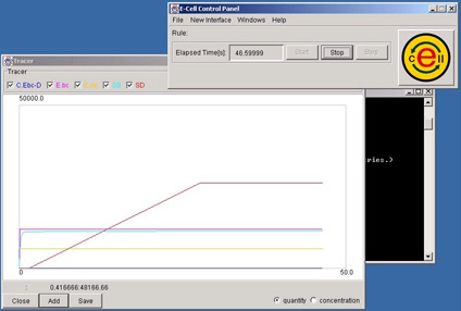
According to a rule described in the Rule File, the quantity of Substances or the activity of Reactors is changed and displayed on the Tracer window. The result of the simulation can be saved by pressing the " Save " button. Refer to Section 3.2.7 for details.
The quantity of a Substance can be changed to watch how the whole system is perturbed by such a forced change. Choose the [Substance Window] item from the [New Interface] menu.
Since this Entry Selector is only for Substance, Reactor can not be selected. Press the " OK " button after selecting a Substance to display a window for the selected Substance.
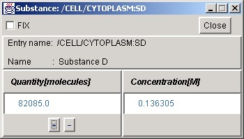
Click the " + " or the " - " button or input a value of the quantity of Substance in the text field to fluctuate artificially. Checking the " Fix " button keeps the quantity through a simulation. Click the " Close " button to quit operation of SubstanceWindow.
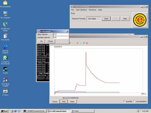
Let's change the quantity of a Substance and see what influence appears in a system.
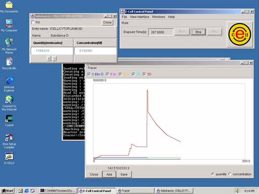
The " Substance D " is increased suddenly in this example. Even if this Substance is increased, it gradually decreases, affected by reactions in the system.
Similarly, the activity of a Reactor can also be shown in details. Select the item [ReactorWindow] from the [New Interface] menu of the Control Panel. A [Entry Selector] window for the Reactor is displayed.

Click System displayed on the left panel as in the case of SubstanceWindow, to look for target Reactors. Click the " Ok " button after choosing Reactors.
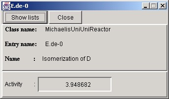
This window displays the name of the Reactor, its employed reaction scheme, and its activity in the current state. Click " Show lists to see more detailed information. When the " Close " button is clicked, the window is closed
Let's click the " Show lists " button.
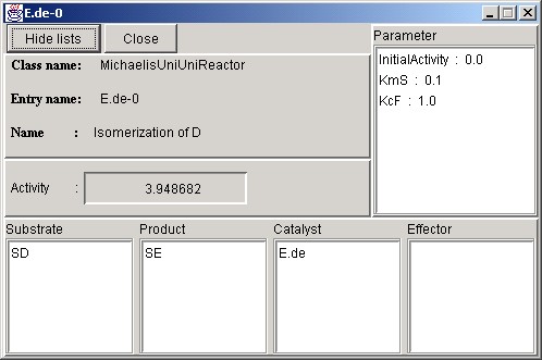
In addition to these information, this expanded window shows initial values for various parameters, and substances, involved in these reactions. Click the " Hide lists " button to change it to the original size, and click the " Close " button to close it.
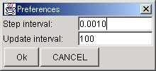
Next, this is the PreferenceWindow. In order to display this window, choose the [PreferenceWindow] item from the [Windows] menu of the Control Panel. This window for setting the step size by second of calculation in a simulation, and for controlling the interval to update the user interface window. If this step size is smaller, the calculation gets more accurate, though it is computationally more expensive. In contrast, the overly longer step size makes calculation faster, but the simulation itself is not trustworthy as a result of coarse accuracy in calculation. In the initial settings, the step size of calculation is set to 0.001 second and the updating timing of the user interface window is set as once in every 100 steps.
Since this window is a dialog box, other windows cannot be manipulated until the " OK " or the " Close " button is clicked.
The message from E-CELL2 is displayed on the MessageWindow. To close this window, click the upper right " x " button.
At present, only the [Version Information] item can be chosen from the [Help] menu of the control panel. The information on the version of E-CELL2 is displayed on the Version Information.
The way to save the state of a simulation is explained in the end of this section. In order to save the progress of a simulation, click the " Stop " button on the Control Panel and select the item [Save Cell State] of the [File] menu.
The extension " .cs " is attached to the file in which the state of the cell model is recorded on the whole. Save it on a suitable directory. A file in this format can be read from the [File] menu of the Control Panel by choosing [Load Cell State], and the user can resume a simulation from the saved state by this mechanism.
In a large-scale simulation, it is serious to do tedious works manually one by one. Then, in E-CELL, a simulation is automatic by using the mechanism of the " script " . The software can interpret the commands for E-CELL, described in the script file. It is usually discriminated by the extension " .ecs " for the script file.
Here, how to write a script is explained briefly and some differences, between E-CELL1 and E-CELL2, are also explained concerning the format of the script file.
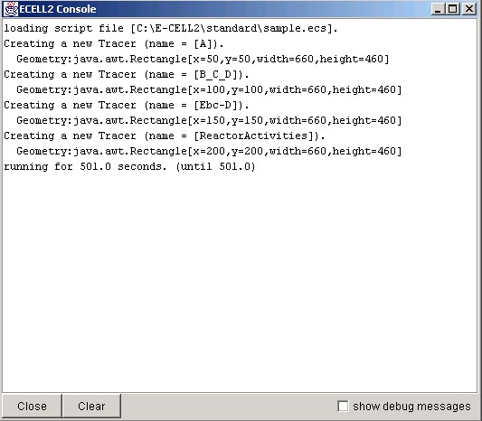
First, see the following file (Each head of the sentence is a line number.).
01  TmpDir /temp
02  LoadRule sample.eri
03
04  NewInterface Tracer A_B_C
05    AddTrace    Substance:/CELL/CYTOPLASM:SA
06    AddTrace    Substance:/CELL/CYTOPLASM:SB
07    AddTrace    Substance:/CELL/CYTOPLASM:SC
08    SaveAt      500
09
10  UpdateInterval 100
11
12  Run 501
13  SaveCellState sample-after500s.cs
14  Stop
line 1: The directory for temporary files
      Here,  " /temp "  means  "the temp directory directly under the current drive "  and it is created at the time of installation.
line 2: Specify the Rule Intermediate File ( " .eri "  file) to be run.
line 4-8: Create a TracerWindow.
line 4-7: The term, " AddTrace "  is declared in the TracerWindow.
	The ID of a Substance or a Reactor, which is the argument of this command, is put on the TracerWindow.  It must be the followed after its System and Type with the delimiter  " : "  in the argument.
line 8: The Substances displayed on this Tracer are saved in 500 seconds of the E-CELL time.  It is declared only within the Tracer term.
line 9:  A blank line is required to break the NewInterface command.
line 10: The TracerWindow is updated every in 100 steps of calculation..
line 12: Simulate for 501 seconds.
line 13: Save the cell-model state to a file  " sample-after500s.cs " .
line 14: Terminate this simulation.
The file, mentioned above, must be saved with a suitable name like " toy.ecs " . Do not use any characters other than US-ASCII. Set the directory to save it to " C:\E-CELL2\standard " , where the file " sample.eri " exists. When E-CELL2 is installed in the directory other than this, please change descriptions in this manual as your environment. Start Cygwin and move to this directory ( " /cygdrive/c/E-CELL2/standard " on Cygwin) using " cd " command.
Start E-CELL2 for the standard-reactor model. The following operations are performed on Cygwin. Input the file name which you created instead of the file " filename.ecs " .
% ./ECELL2.BAT -f filename.ecs
Use the " -f " option in order to load a script file to E-CELL2 from the command line. Since it is convenient to try many simulations, keep it in mind.
What do you see now?
To change topics, the mechanism of " Logger " , equipped newly in E-CELL2, is introduced here. The Logger is the mechanism which records the state of a cell in every step during a simulation. It is more advanced rather than saving the state of a cell like a snapshot. It can be used by adding the following description to a script file.
NewInterface Logger test-log
  AddTrace    Substance:/CELL/CYTOPLASM:SA
  AddTrace    Substance:/CELL/CYTOPLASM:SB
  AddTrace    Substance:/CELL/CYTOPLASM:SC
  AddTrace    Substance:/CELL/CYTOPLASM:SD
  AddTrace    Substance:/CELL/CYTOPLASM:E.bc
  AddTrace    Substance:/CELL/CYTOPLASM:C.Ebc-D
  AddTrace    Reactor:/CELL/CYTOPLASM:E.ab-0
  AddTrace    Reactor:/CELL/CYTOPLASM:E.bc-0
  AddTrace    Reactor:/CELL/CYTOPLASM:E.cd-0
Add the description of the Logger after the 9th line of " .ecs " file, and make E-CELL2 read it.
The following are the features of the Logger.
After the simulation stopped, open any " .ecd " file below the Logger directory with an editor program such as notepad. The file name means a corresponding Substance or Reactor and the numeric values on " time " , " number of moments " , " number of averages " , the " maximum number " , " minimum number " , " moment concentration " , " average concentration " , " maximum concentration " , and " minimum concentration " of the specified entity. For details, please refer to Section 3.3.4.
The user must design and develop a Reactor for E-CELL2 if a chemical reaction of interest , which is not covered by standard reactors.
An RD file is composed of rational pairs of keywords and values to describe a chemical reaction scheme.
An RD file can be divided roughly into three parts;Please pay attention to the following rules in making a Reactor Description File.
The example of the RD file is shown below.
| v = | KcF[E][S] | |
|
||
| KmS + [S] |
MichaelisUniUniReactor
|
The above is brief explanation for the Reactor. Please refer to Chapter 5 for the details of the Reactor.
A simple example is given to explain how to create a Reactor. First, start Cygwin and change current directory to " tools\reactor " using the " cd " command. This directory is located in " C:\E-CELL2\standard\tools\reactor " in standard installation. On Cygwin, this directory is as follows.
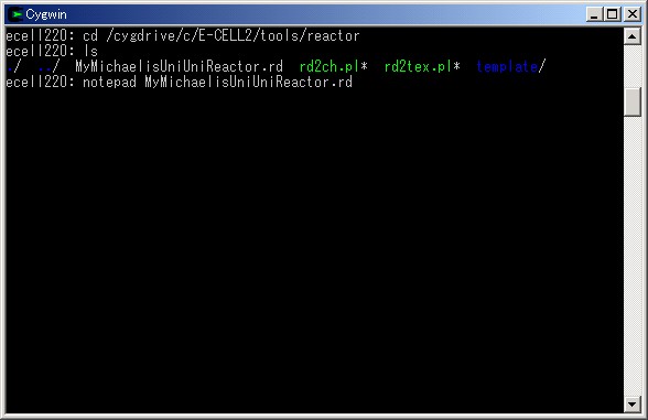
List the contents of this directory to find out the file " MyMichaelisMentenUniUni.rd " . Let's open this by the program " notepad "or your favorite text editor. A Reactor Description File (RD file) is created as a file which usually has the extension " .rd " . The definition of a reactor is described in this file.
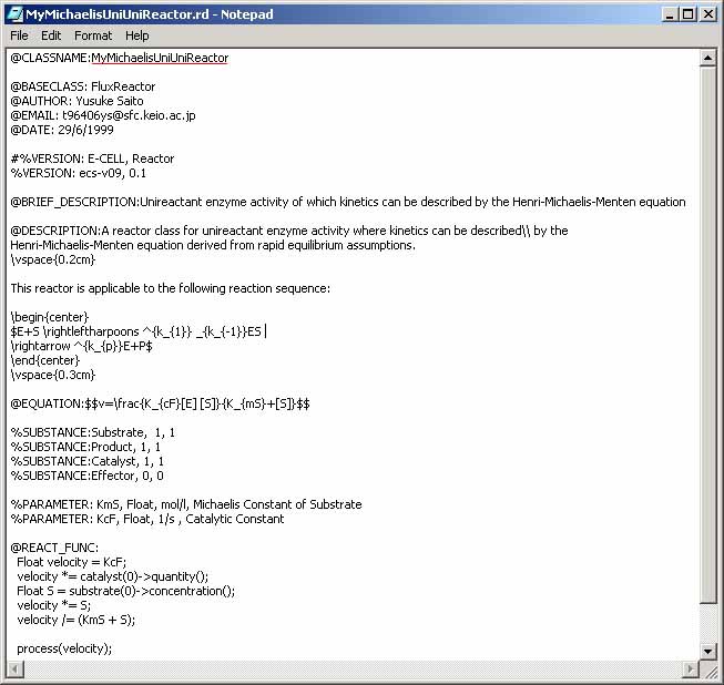
As the first step of making a Reactor Description File, note that the filename except extension should agree with its @CLASSNAME. The file, or MyMichelisMentenUniUniReactor.rd, is the same with MichaelisMentenUniUniReactor.rd except for the class name. The description files of standard reactors are in " C:\E-CELL2\standard \STDR " in standard installation. It is good for the user to refer their descriptions when the user's own Reactor is needed.
The C++ source code and the header file are converted from the Reactor Description File by " rd2ch.pl " .
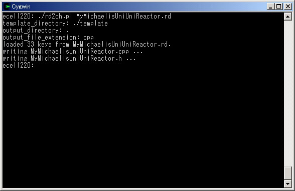
Confirm " MyMichaelisMentenUniUniReactor.h " and " MyMichaelisMentenUniUniReactor.cpp " were generated. Make copies of these files and send them to " C:\E-CELL2\standard\SRCR " . When E-CELL2 is installed in another directory, please interpret it suitably as your situation. This directory is for placing the source codes and header files of Reactors.
Concerning the tools supporting for creation of a Reactor, it will be also convenient if they are available anywhere on Cygwin. The PATH environment variable must include the absolute directory path for these tools, to fulfill this dream. By default, the directory path is " C:\E-CELL2\tools\reactor " , or " /cygdrive/c/E-CELL2/tools/reactor " on Cygwin. The script " rd2ch.pl " requires several template files to generate the source code and the header file for a designated Reactor. These templates are in the " template " directory immediately below one where " rd2ch.pl " exists. Therefore, specify the directory path for templates explicitly with the option " -t absolute_path_for_templates " , to use this script in other places on condition that the PATH variable is correctly configured. By default, the absolute path for templates is " C:\E-CELL2\tools\reactor\template " , or " /cygdrive/c/E-CELL2/tools/reactor/template " on Cygwin. This configuration makes one free from writing " ./ " at the head of a command to show " of the current directory " .

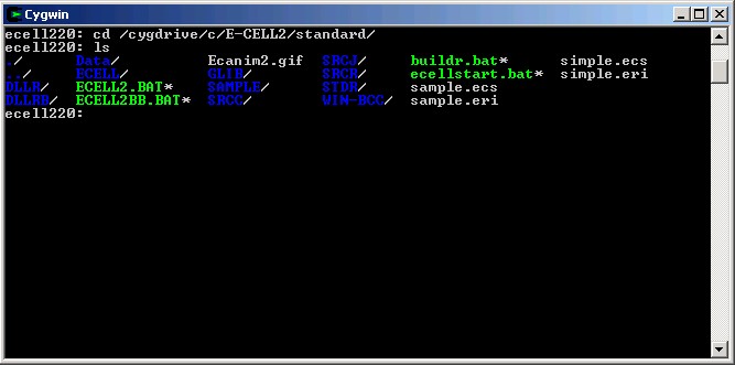
Change current directory to the directory for E-CELL2 of standard reactors, and list the items there. Check that there is a file copied previously.
In order to add a Reactor to the system, it is necessary to compile the source code and the header file of the " MyMichaelisMentenUniUniReactor " class, and generate " MyMichaelisMentenUniUniReactor.dll " , which must be moved and placed appropriately. Such works are carried out by executing " buildr.bat " . Open this file by the program notepad.
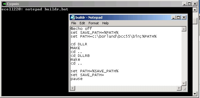
Here, rewrite the contents of this file so that " bin " of Borland C++ Compiler comes to the head in PATH. Execute the following command on Cygwin if the location is unknown. If its setup was done correctly, location of Borland C++ Compiler will turn out.
% which bcc32
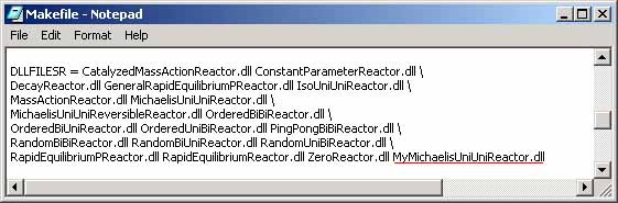
The batch file " buildr.bat " uses the tool " MAKE " for compiling the source code and the header file of a Reactor, added newly. Since " MAKE " compiles them according to " Makefile " in " C:\E-CELL2\standard\DLLR " , it also needs to rewrite this file. When installation was not standard, interpret a directory path suitably. Move to the directory, display files using " ls " , and check if there is a " Makefile " . Open the Makefile by notepad.
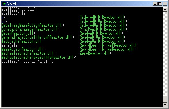
A part of description of Makefile is shown here. The entity of the " MyMichaelisMentenUniUniReactor " class is set to " MyMichaelisMentenUniUniReactor.dll " , so add this file name to the end of " DLLFILESR= " .
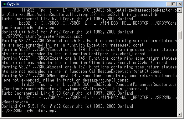
In order to use the " buildr.bat " file, go up to the directory above and perform this batch file.

If the setup of Borland C++ Compiler was performed appropriately, although warning messages, compilation continues without stopping.
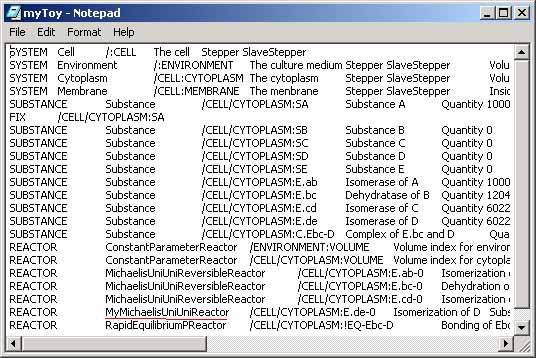
If compilation is finished, let's use " MyMichaelisMentenUniUniReactor " actually. Since " sample.eri " is in this directory, copy it to " myToy.eri " and open it by notepad.

Open " myToy.eri " by notepad and substitute the field " MichaelisMentenUniUniReactor " to " MyMichaelisMentenUniUniReactor " , and save it.
Start E-CELL2 and load " myToy.eri " by selecting [Load rule] from [File] menu to start a simulation. It is successful if the behavior is not different from that of " sample.eri " .
From now on, design and develop Reactors as circumferences demand and teach yourself to perform an original simulation.
All of the procedures for the simulation of E-CELL2 have been completely outlined. Refer to the following chapters for further explanation on each topic.
|
|
E-CELL2 User's Manual
Last Update $Date: 2002/07/16 16:45:42 $. Copyright: Keio University and Mitsui Knowledge Industry Co., Ltd. 2002 |
Chapter 2 Tutorial [ Chapter 1 : Chapter 3 : Chapter 4 : Chapter 5 ][ Top ] |