[Chapter 1:Chapter 2:Chapter 3:Chapter 5:Chapter 6][Top]
| E-CELL2 User's Manual | Chapter 4: Creating Rule Files [Chapter 1:Chapter 2:Chapter 3:Chapter 5:Chapter 6][Top] |
Rule files are data files used to define the models to simulate in E-CELL2. In this file, enzymatic and substance related data are included with their inner-relations (reactions) network and environment settings such as the cell volume. Users can also edit Reactor files to define the kinetic equation of the reaction (Details in Chapter 5) and define the necessary substance and parameters in that Reactor inside the Rule file.
There are three types of Rule files:
Rule files can be written in spreadsheet format (ss) or directly as text (er). While writing rules as ss files under general spreadsheet programs or the model launcher are visually and simplicity-wise advantageous, er files can easily be batch-manipulated under script programs and macros. In any case, they will eventually be converted to eri files (where ss files must first be converted to er files before eri).
Rules files are divided into 4 sections: the System section (define the model environment for simulation), the Substance section (define substance name and value), the Reactor section (define reactions and inner-relation networks), and the Include section (to import other er files). These sections are not required to be in a single file or in this order. This chapter describes the methods in creating rule files in spreadsheet format.
In this section, the required 4 sections with their lemmatizing lines will be described step-by-step by actually creating a rule file.
Note here that using the following in the columns are prohibited, for these are used to separate the items in the spreadsheet program.
Including these may cause an adverse effect to the eri converting process.
Lemmatizing words are required for starting a new section. The columns with these lemmatizing words are called the "Lemmatizing Columns" where they must be included before starting a new section. The blue columns in Figure 1 are the lemmatizing columns, where the items are case/order-insensitive. Users can add a "memo" item to write down comments which will not be included in the eri conversion process.
The System Section sets the simulation system architecture and the environment which are required to perform a simulation: the destination and the volume of the simulation target (System). Below are the descriptions:
|
||||||||||||||||||||||||||||||
Input [System] in the Type row, and the destination of the system and class in the Class row. Cell, Environment, Cytoplasm, and Membrane can be defined as Class in this row. While these Classes are able to handle Substance, Reactor and Volume inside itself, Environment and Membrane cannot create a System under itself. Each Class is able to hold the following items:
|
||||||||||||||||||||||||||||||
Figure 5: Systems Section [path row]
The path row defines the destination of the System created, acting as an address. Paths start with a RootSystem (/), the uppermost directory of the E-CELL2 System, and continue with user defined directories. Paths are divided up with single front-slashes (/system1/system2/system3 and so forth) and must be written as absolute paths. This section cannot be left blank. Note also that this section is case-sensitive.
FQEN (FullyQualifiedEntryName) is a method to define the destinations for System, Substance and Reactor items in a hierarchical system, Using this method, the destination can be written as "/system0/system1/system2:ID", where the path and the ID are separated with a colon (:). If the path is "/CELL/CYTOPLASM" and the ID is "ATP", the FQEN would be "/CELL/CYTOPLASM:ATP".
FQEN cannot tell the difference among the System, Substance and Reactor items.
FQPN adds these item name into the statement. In FQPN, the target is described
as [Type]:[FQEN]. In the former example of ATP, the target in FQPN will be "Substance:/CELL/CYTOPLASM:ATP".
Note that FQPN is case-sensitive.
IDs are used as process orders inside the E-CELL2 simulation software. Thus, if duplicate IDs are defined inside a System, a warning message will be displayed and the former defined ID will be used only. Note that ID must be defined as case-sensitive.
Define the ID of the System(location) in the ID row and the name of the System in the Name row.
inside/outside rows are used in defining Systems inside or outside of the membrane (if the defined Class is Membrane). Although current E-CELL2 System cannot process these information, it will be dealt with in further versions by limiting the accessibility for each System. Figure 7 is an example of this, a System of MEMBRANE framed by CYTOPLASM and ENVIRONMENT.
In the E-CELL2 System, the System volumes are defined as Reactors. When destinating FQEN of the Reactor as System's VolumeIndex, the activity value of the Reactor will be used as the volume of the System (in Liters). When destinating VolumeIndex of the System, the Reactor FQEN in correspondence must also be defined in the Reactor part.
Although System may or may not have a volume (Membrane in the above example do not have a volume), their volume and the VolumeIndex is required in cases where Reactors use the substance concentrations for calculations or the Substance section uses Conc as the substance value(to recalculate the molecular amount)
Substance Section in the rule file is used to define all of the Substances involved in the simulation. The definition for each item is as follows:
|
|||||||||||||||||||||||||||||||||
Define "Substance" in the Type row with the type format in the Class row. For current version only supports "Substance" as Class, always input "Substance" as Class (it will be automatically inserted if left blank)
Define the location(System) of the Substance in the path row. The format is identical to the System section with front-slash seperators (/system1/system2/system3). Note that Substances with the same ID and Names in different Systems are treated as different elements in E-CELL2 System. Note also that this section is case-sensitive.
Define ID and the Name of the Substance, (Case-sensitive)
Qty defines the initial molecular amount of the substance in the user defined volume. Qty cannot coexist with Conc; displays a Warning message and adopts the Qty value. If neither values are inputted, Qty will start as 0. It is also possible to fix the Qty value at a certain amount (refer to the later sections).
For Conc, define the concentration values in M(mol/l). While converting er files to eri, these values will be used for the "init_act" of Reactor defined in the Volume part of the System section with the Avogadro's constant (6.0221367e23) to be converted to molecular amount. Conc cannot coexist with Qty; Qty value will be used in the eri if none is inputted in Conc. Note that having no VolumeIndex for System sections with substances result with the System Volume equal to 0. Conc value can be fixed.
Fix function manipulates the Substance Column so that the substance will not
get the influence of the Reactor to fix the inputted Qty or the Conc value.
To fix these values, input "Fix" under the Qty/Conc value.
Accumulator describes the method in rounding off the decimal points. Defining "Accumulator" for Arg_tag selects the method. Arg_coeff describes the specifics in selecting the actual rounding method; choosing multiple methods for calculations have no proof in accuracy.
Select the capsulated Accumulator Class for rounding decimal points in Substance
and define in Arg_coeff. Below are the selectable choices:
|
||||||||||||||||||||||||||||||||||
The Reactor Section is to select the environment variables such as the reactions(using substances defined in the Substance sections), inter-relationships, and volume. In this section, the Reactor will be stoichiometrically defined with the involved Substances. Below are the specifications.
|
|||||||||||||||||||||||||||||||||||||||||||||||||||||||||||||||

Reactor Types (Class: Kinetic Equations) are defined in the class row. In the row, the Reactors must be written as ???Reactor name format. (The Example below describes the MichaelisMenten related equations, and thus are written as Michaelis???Reactor, each defining Reactor items with Volume) Please refer the spec sheet for other predefined Reactors. Define the ID for the reaction (or the interrelations). Note that the items must be written case-sensitive.

Figure 20: Reactor Section [path row]
Define the System Path for the reactions or the interactions in the Path row. Similar to the paths for the Substance section, it can be observed below that the Reaction occurs under /CELL/CYTOPLASM. Note that the texts are case-sensitive.

Name rows are to define the names for the reactions or the interactions. The ID will be the name for the eri file if this is left blank. For Reactors with volume, it is desired for that Reactor to have names that can be understood as volume-related (see chapter 3 for details). However, for FluxReactor (or in any case where the IDs start out with an "!"), the behavior is non-guaranteed.

Figure 22: Reactor Section [init_act row]
For Reactor activities that get calculated 1 step after the another, these Reactor activity values need to be set at the start of the simulation. init_act row is to input those initial values, where in defining Reactors pointed in the VolumeIndex of the System section it is always required. This init_act will be used initially as Reactor activity values before starting the simulation. The Volume to be used in every reaction inside the model will be set as 0 at the first step initial point of the simulation, if no value exist here --- disabling the simulation. The initial Volume in the example below is defined in the ConstantParameterReactor of the Reactor (defining volume) inside the System.
S_ID and S_Path defines the Substrate ID and its path of the System (location). In the reaction below, ATP and Glc are the substrates (under CYTOPLASM) in the reaction. Define the stoichiometric coefficient of the Substrate in S_Coeff.
P_ID and P_Path defines the Product ID and its path of the System (location). In the reaction below, ADP and G6P are the products (under CYTOPLASM) in the reaction. Define the stoichiometric coefficient of the Product in P_Coeff.
C_ID defines the catalysts influencing Substrates and Products inside the reaction. C_Path defines the Catalyst System (location) Path. In default, the ID and the Path for the catalysts will be identical with the reaction's ID and Path.

In the arg_tag row, the constant name that the kinetic equation will use as a parameter must be defined. This constant name is must exist for each Reactor; in the example above, the second-last Reactor uses "MichaelisUniUniReactor" as the kinetic equation which make the arg_tag "KcF and KmS". (Refer to the spec sheet for specifications on general reactors) If multiple parameters exist, write them in the row under the another, and no other data must be defined for that row (see example). Note that this section is also case-sensitive. For ConstantParameterReactor (For calculating the Volume of the Reactor), insert Value in the Arg_tag.
Also, users are able to define any Effectors that exist in the reaction where the amount itself is not influenced by that reactor. Define the Substance ID and its System(location) path under E_ID and E_Path. Define the stoichiometric coefficient of the Effector in E_Coeff. Refer to the Reactor chapter for more information.

By including an Include Section in the rule, it is possible to import other er files into the ERI conversion. As similar with other sections, the Include section can be placed many times at any position. This function is usable in cases where general lines that must be included. The Include Section need not be included if there are no files that need to be imported. The lemmatizing words are "Type" and "Filename". Define [Include] as Type and the actual filename under Filename. The above example is importing the file "simple.er".
To convert to ERI file which can be read in the E-CELL2 System, the input file must be in a tab separated text format that the converting software can recognize. To create such a text file, it is desired to use the spreadsheet creating function of the ModelingLauncher or general software such as Microsoft Excel. A sample for the ss file can be found under the standard directory with the .txt extensions. In the basic install, the directory will be C:\E-CELL2\standard. ModelingLauncher which can be used for creating rule files can be executed with the ModelingLauncher shortcut or from Programs->E-CELL2->ModelingLauncher in the Start menu. Refer to Chapter 6 for more details.
In order to perform simulations with the E-CELL2 System, it is required to convert the ss files (or the er files) into eri format. Launch the ModelLauncher, select the Rule tab, and select "Choose..." from the "File..." button on the right.
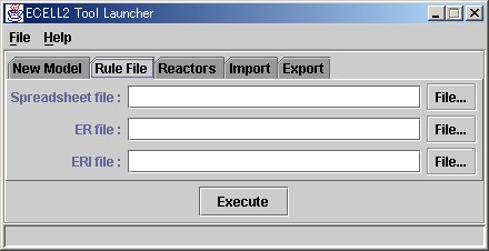
After selecting the input file from the file window, eri file will be created
from pressing the Execute button. In the GUI version, By selecting "Load
Rule" from the "File" menu loads up the file for input. Refer
to chapter 3 on loading E-CELL2.
| E-CELL2 User's Manual Last Update $Date: 2003/3/20 $. Copyright: Keio University and Mitsui Knowledge Industry Co., Ltd. 2000-2003 | Chapter 4: Creating Rule Files [Chapter 1:Chapter 2:Chapter 3:Chapter 5:Chapter 6][Top] |